
Contents
Op-Amp Adder and Subtractor Circuits
The adder can be obtained by using either non-inverting mode or differential amplifier.
Here the inverting mode is used. So the inputs are applied through resistors to the inverting terminal and non-inverting terminal is grounded.
This is called “virtual ground”, i.e. the voltage at that terminal is zero.
The gain of this summing amplifier is 1, any scale factor can be used for the inputs by selecting proper external resistors.
Adder Circuit:-
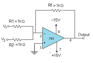
- Connect the circuit as per the diagram.
- Apply the supply voltages of +15V to pin7 and pin4 of IC741 respectively.
- Apply the inputs V1 and V2 as shown.
- Apply two different signals (DC/AC ) to the inputs.
- Vary the input voltages and note down the corresponding output at pin 6 of the IC 741 adder circuit.
- Notice that the output is equal to the sum of the two inputs.
Readings:
| V1 | V2 | V o/p |
| 2 | 2 | -4.06 |
| 5.8 | 2 | -8.04 |
Calculation: Adder
- Vo = – (V1 + V2)
- If V1 = 2V and V2 = 2V, then
- Vo = – (2+2) = -4V.
Subtractor:
The subtractor circuit, input signals can be scaled to the desired values by selecting appropriate values for the resistors.
When this is done, the circuit is referred to as scaling amplifier. However in this circuit all external resistors are equal in value.
So the gain of amplifier is equal to one. The output voltage Vo is equal to the voltage applied to the non-inverting terminal minus the voltage applied to the inverting terminal; hence the circuit is called a subtractor.
Subtractor circuit
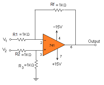
1. Connect the circuit as per the diagram.
2. Apply the supply voltages of +15V to pin7 and pin4 of IC741 respectively.
3 Apply the inputs V1 and V2.
4. Apply two different signals (DC/AC ) to the inputs.
5. Vary the input voltages and note down the corresponding output at pin 6 of the IC 741 subtractor circuit.
6. Notice that the output is equal to the difference of the two inputs.
Readings:
| V1 | V2 | V=o/p |
| 4 | 2 | -2 |
| 3.1 | 5.7 | -2.67 |
Calculation: Subtractor
- Vo = V2 – V1
- If V1=4 and V2 = 2, then
- Vo = 4 – 2 = -2


Hi… in the subtractor, why there is a need of having R3 in the circuit.
Hello,
In subtractor, what would be the output if both V1 and V2 are negative?
For example say V1= (-3V) and V2= (-5V), Vo=?
Follow the above circuit the results of the op-amp output result shows in negative voltage but input is positive.
Apply negative voltage V1= (-3V) and V2= (-5V),
Result is Positive 2V.
How can you apply negative voltage to inputs
-3-(-5)=-3+5=2
Sr Va and Vb ko ek voltage source se connect katne ka tarika kya hai