Ramp and Pedestal Triggering Circuit Diagram
Ramp and Pedestal Triggering Circuit Diagram The circuit for ramp and pedestal triggering of two SCR’s connected in antiparallel for controlling power in an AC…

Ramp and Pedestal Triggering Circuit Diagram The circuit for ramp and pedestal triggering of two SCR’s connected in antiparallel for controlling power in an AC…
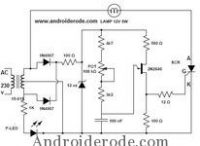
UJT Triggering Circuit The supply voltage of the secondary winding of transformer is rectified by the half wave rectifier diodes and given to the zener diode.…

Ex-NOR Logic Gate Animation Video Tutorial The logic gate is a digital circuit with one or more inputs, with only one outputs. The…
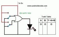
Logic OR Gate Animation The OR gate has two or more inputs and a single output. Ia performs logical addition. The OR gate…
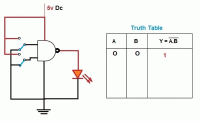
EX-OR Gate Animation The EX-OR gate has only two inputs and one output. It produces a High output when the two inputs are…

LOGIC NOR GATE ANIMATION The Transistor Transistor Logic (TTL) NOR gate is a combination of OR gate followed by a NOT gate. The output is LOW, when any…


