
Contents
How to test UJT with Digital multimeter?
A uni junction transistor (UJT) is an electronic semiconductor device that has only one junction.
The UJT has three terminals: an emitter (E) and two bases (B1 and B2). The base is formed by lightly doped n-type bar of silicon.
Two ohmic contacts B1 and B2 are attached at its ends. The emitter is of p-type and it is heavily doped.
The resistance between B1 and B2 when the emitter is open-circuit is called inter base resistance.
SYMBOL

- The original uni junction transistor, or UJT, is a simple device that is essentially a bar of N type semiconductor material into which P type material has been diffused somewhere along its length, defining the device parameter .
- The 2N2646 is the most commonly used version of the UJT.
- The complementary uni junction transistor, or CUJT, that is a bar of P type semiconductor material into which N type material has been diffused somewhere along its length, defining the device parameter .
- The 2N6114 is one version of the CUJT.

HOW TO TEST UJT WITH DMM?
STEP-1.
- …Select DMM to Diode Mode
- Connect DMM positive test lead to Emitter UJT 2N2646 Pdf Details: UJT-2N2646-datasheet & Circuits
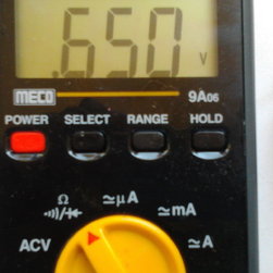
- ………….DMM Negative test lead to Base-1 = Display reading shows .650v
- ………….DMM Negative test lead to base-2 = Display reading shows .735v
STEP-2.
Connect DMM Negative test lead to Emitter How to use the Digital multimeter?
- DMM positive test lead to Base-1 OL DMM READING SHOWS open
- DMM positive test lead to Base-2 OL open
- DMM Negative test lead to Base-1 0.874v
- DMM Negative test lead to Base-2
- DMM Positive test lead to Base -1 0.947v or (947 mV).
Verification:
If you get reading in forward bias as 0000 or OL or 1, and in reverse bias as 0000 (or) low values the the DEVICE can be FAULTY and needs replacement.
Verification:
If the DMM above reading shows the condition is GOOD.
Required components are needed to get below wave form,
2. R1=100K TO OHMS TO 220K OHMS (Variable pot 220k with series R= 470, OHMS)
3. R=47 OHMS,
4. 0.47 Mfd
UJT – R & C Trigger Circuits.


hi.. is there a transistor tester for PUT/UJT, where the device will be put in a tester then it will readout the readings?